Brand
:
Pololu
Product Code
:


(mm) |
output | optimal range |
|||
|---|---|---|---|---|---|
| LED | |||||
| 1 | 5.0 × 20.0 | analog | 3.5 mA | 10 mm | |
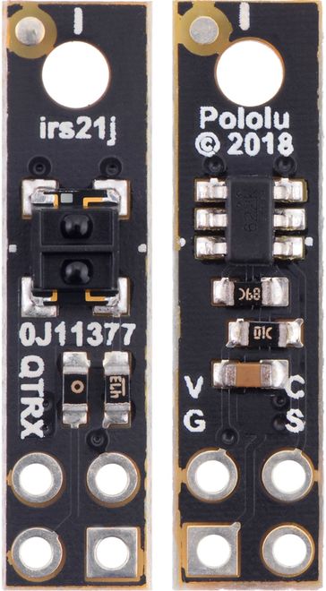
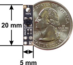
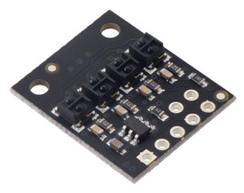
This IR LED/phototransistor pair is great for precisely identifying changes in reflectance (like line detection). It operates from 2.9 V to 5.5 V and offers dimmable brightness control independent of the supply voltage. In general, the closer the object, the higher the contrast between light and dark readings, but high-reflectance objects are generally detectable out to around 30 mm. This version features a high-performance, low-current QTRX sensor with lenses.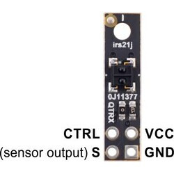
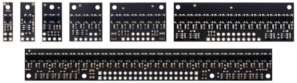
These reflectance sensors feature a linear array of infrared emitter/phototransistor pair modules in a high-density (4 mm pitch) or medium-density (8 mm pitch) arrangement, which makes them well suited for applications that require detection of changes in reflectivity. This change in reflectivity can be due to a color change at a fixed distance, such as when sensing a black line on a white background, as well as due to a change in the distance to or presence of an object in front of the sensor. A variety of sensor counts and densities is available so you can pick the ideal arrangement for your application. Since the outputs are all independent, you can connect just some of the channels to attain an irregular or non-standard sensor spacing.
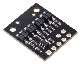
Two different sensor options are available, denoted by “QTR” or “QTRX” in the product name. The “QTR” versions feature lower-cost sensor modules without lenses while the “QTRX” versions feature higher-performance sensor modules with lenses, which allow similar performance at a much lower IR LED current. You can see the two different sensor styles in the pictures below of the 4-channel modules:
We also have several single-channel modules with the “QTRXL” designator that offer extra-long range by using the QTRX-style sensor module with higher current through the emitter.
Our Arduino library makes it easy to use these sensor modules with an Arduino or compatible controller by providing methods for controlling the emitters, calibrating the module, and reading the individual sensor values from either the A or RC versions. It also has a method specifically for line-following applications to compute the location of the line under the array.
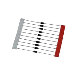
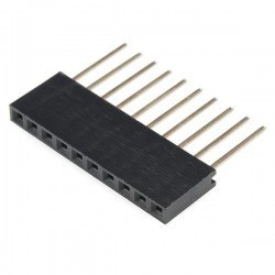
Note: Unlike most of our products, these sensor arrays do not ship with any headers or connectors included, so you will need to supply your own or solder wires directly to the board to use it. See our selection of male headers, female headers, and pre-crimped wires for various connector options.
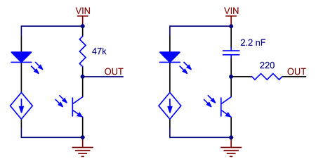
Each sensor on the A versions outputs its reflectance measurement as an analog voltage that can range from 0 V when the reflectance is very strong to VCC when the reflectance is very weak. The typical sequence for reading a sensor is:
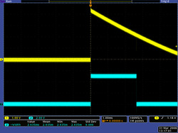
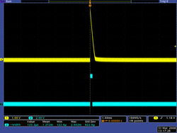
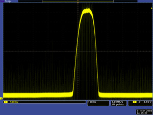
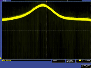
This last method will work if you are able to get high reflectance from your white surface as depicted in the left image, but will probably fail if you have a lower-reflectance signal profile like the one on the right.
Each sensor on the RC versions requires a digital I/O line capable of driving the output line high and then measuring the time for the output voltage to decay. The typical sequence for reading a sensor is:
|
|
These steps can typically be executed in parallel on multiple I/O lines.
With a strong reflectance, the decay time can be as low as a few microseconds; with no reflectance, the decay time can be up to a few milliseconds. The exact time of the decay depends on your microcontroller’s I/O line characteristics. Meaningful results can be available within 1 ms in typical cases (i.e. when not trying to measure subtle differences in low-reflectance scenarios), allowing up to 1 kHz sampling of all sensors. If lower-frequency sampling is sufficient, you can achieve substantial power savings by turning off the LEDs. For example, if a 100 Hz sampling rate is acceptable, the LEDs can be off 90% of the time, lowering average current consumption from 125 mA to 13 mA.
These reflectance sensor arrays maintain a constant current through their IR emitters, keeping the emitters’ brightness constant, independent of the supply voltage (2.9 V to 5.5 V). The emitters can be controlled with the board’s CTRL pins, and the details of the control depends on the array size and density:
Driving a CTRL pin low for at least 1 ms turns off the associated emitter LEDs, while driving it high (or allowing the board to pull it high) turns on the emitters with the board’s default (full) current, which is 30 mA for “QTR” versions and 3.5 mA for “QTRX” versions. For more advanced use, the CTRL pin can be pulsed low to cycle the associated emitters through 32 dimming levels.
|
|
level (pulses) |
current (%) |
Dimming level (pulses) |
Emitter (%) |
|
|---|---|---|---|---|
| 0 | 100.00% | 16 | 46.67% | |
| 1 | 96.67% | 17 | 43.33% | |
| 2 | 40.00% | |||
| 3 | 90.00% | 36.67% | ||
| 86.67% | 33.33% | |||
| 5 | 83.33% | 21 | 30.00% | |
| 6 | 80.00% | 22 | 26.67% | |
| 7 | 76.67% | 23 | 23.33% | |
| 8 | 73.33% | 24 | ||
| 9 | 70.00% | 25 | ||
| 10 | 66.67% | 26 | 13.33% | |
| 63.33% | 27 | 10.00% | ||
| 60.00% | 28 | 6.67% | ||
| 13 | 56.67% | 29 | 5.00% | |
| 14 | 53.33% | 3.33% | ||
| 15 | 50.00% | 31 | 1.67% |
For example, to reduce the emitter current to 50%, apply 15 low pulses to the CTRL pin and then keep it high after the last pulse.
| Size: | 5.0 × 20 × 4.4 mm |
|---|---|
| Weight: | 0.25 g |
|
Maximum range:
|
30 mm |
|---|---|
|
Optimal range:
|
10 mm |
|
Minimum operating voltage:
|
2.9 V |
|
|
5.5 V |
|
|
3.5 mA1 |
|
Peak wavelength:
|
940 nm |
|
|
5 mA2 |
|
Sensor type:
|
|
|
Sensor count:
|
1 |
|
|
A (analog voltages) |
| irs21j3 | |
| Other PCB markings: | 0J113773 |
Information about using the Pololu QTR reflectance sensors, including differences between A-type and RC-type sensors and sample oscilloscope screen captures of sensor outputs.
Recommended links